Computer Networks · TEE · papers
Q2(b)(ii) · CRC encoder and decoder
2022-11-16 · AI-only Sem V
Exact historical variant. Current-syllabus questions solved; excluded topics and source limitations stated.
Q2(b)(ii). Explain the principle and working of cyclic redundancy check with a neat encoder and decoder diagram. [6 marks]
Answer
A Cyclic Redundancy Check (CRC) treats a binary message as a polynomial over GF(2). Addition and subtraction are XOR: 0⊕0=0, 1⊕0=1, 0⊕1=1, 1⊕1=0. There are no carries or borrows. A degree-r generator contains r+1 bits, with leading and constant coefficients 1.
 LaTeX:
T(x)=x^rM(x)\oplus R(x),\quad R(x)=x^rM(x)\bmod G(x)- Convert each polynomial coefficient into a bit, including zero coefficients for missing powers.
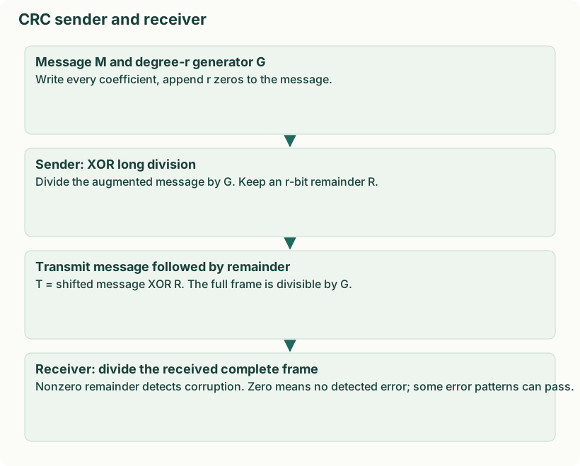
- Append r zero bits to the message, because multiplying by x^r shifts it left r places.
- Align the generator’s leading 1 with the current leading 1; XOR and repeat until fewer than r+1 significant bits remain. Pad the remainder to exactly r bits.
- Replace the appended zeros with the remainder. The resulting transmitted frame is divisible by the generator.
- The receiver divides the entire received frame by the same generator without appending more zeros. A nonzero remainder proves a detected error. Zero means no error detected; a nonzero error polynomial divisible by the generator can pass.
A degree-r generator with nonzero constant term detects every burst of length at most r. Generators containing factor (x+1) detect every odd number of bit errors. Longer-error guarantees depend on the polynomial and frame length; CRC is not a general correction method.
Yaad rakho: CRC mein subtract bhi XOR; receiver par full frame divide.
| Data + r zero bits | → | Modulo-2 divide by generator | → | Append r-bit remainder | → | Receiver divides full codeword | → | Zero remainder: no detected error |