Computer Networks · TEE · papers
Q2(a) · Network topologies
2025-12-05 · 2022-23
Actual paper; 100 marks attempted. Current-syllabus alignment is stated per question.
Q2(a). Explain the topologies used in computer networks. Give specific examples of each and compare them on the basis of advantages and disadvantages. [10 marks]
Answer
Topology is the arrangement of nodes and links. Physical topology describes actual links; logical topology describes how data flows. A switch-centred physical star is different from a shared collision-domain bus.
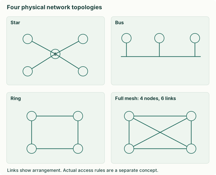
Diagram: Four physical network topologies. Labels: Four physical network topologies | Four physical network topologies | Star | Bus | Ring | Full mesh: 4 nodes, 6 links | S | Links show arrangement. Actual access rules are a separate concept.
| Topology | Structure | Benefit | Limitation |
|---|---|---|---|
| Bus | Devices share a common backbone | Simple small shared-medium layout | Backbone fault affects segment; collisions possible on classic shared bus |
| Star | Each device connects to a central switch/hub | Easy expansion and fault isolation | Central-device failure affects star; more cabling |
| Ring | Each node connected to two neighbours in a ring | Structured traversal; token-based variants coordinate access | Simple single-ring break can disrupt operation unless protected |
| Full mesh | Every pair has a direct link | Redundant paths and direct connectivity | Expensive ports/cabling: n(n−1)/2 undirected links |
| Tree/hybrid | Hierarchical stars or combined topologies | Scales into buildings/floors | Upper-level faults affect dependent branches |
Yaad rakho: Layout draw karo, then one strength and one failure case.
Two advantages and two disadvantages of each topology
| Topology / example | Advantage 1 | Advantage 2 | Disadvantage 1 | Disadvantage 2 |
|---|---|---|---|---|
| Star: switched computer laboratory | A device can be added on a spare central port without rebuilding the whole topology | A single access-cable fault normally isolates only its attached device | Central-switch failure affects all attached devices unless redundant | A separate cable and switch port are needed per device |
| Bus: legacy coaxial Ethernet | Uses little cable in a small linear layout | No central switch is required in the simple shared-bus design | A backbone fault can disable the segment | Shared bandwidth, contention and fault diagnosis become difficult as it grows |
| Ring: token-based ring | Controlled token access avoids data collisions among compliant stations | Token rotation gives stations an organized opportunity to transmit | A break can interrupt an unprotected single ring | Adding/removing a node can disrupt a simple ring |
| Mesh: redundant router backbone | Alternate links preserve connectivity after some link failures | Direct pairwise links can carry separate exchanges without a shared central bottleneck | A full mesh needs n(n−1)/2 links and many ports | Configuration, cabling and maintenance become complex |
The ring benefits above assume token-controlled access; physical ring wiring alone does not guarantee fairness or collision avoidance. The failure disadvantages describe simple layouts without protection/redundancy.